Boeing 737 Cockpit
(work in progress...)
Content:
|
|
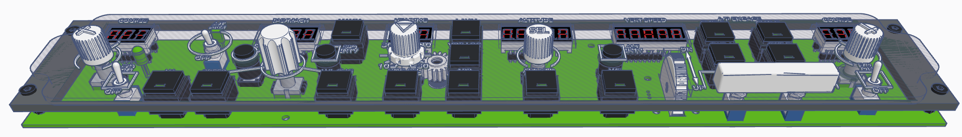
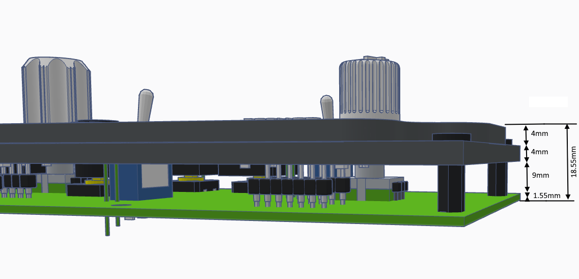
MCP
Faceplate
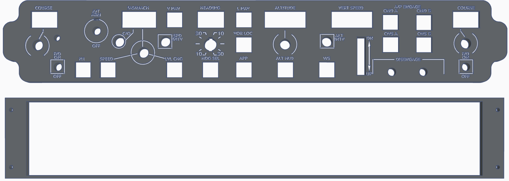
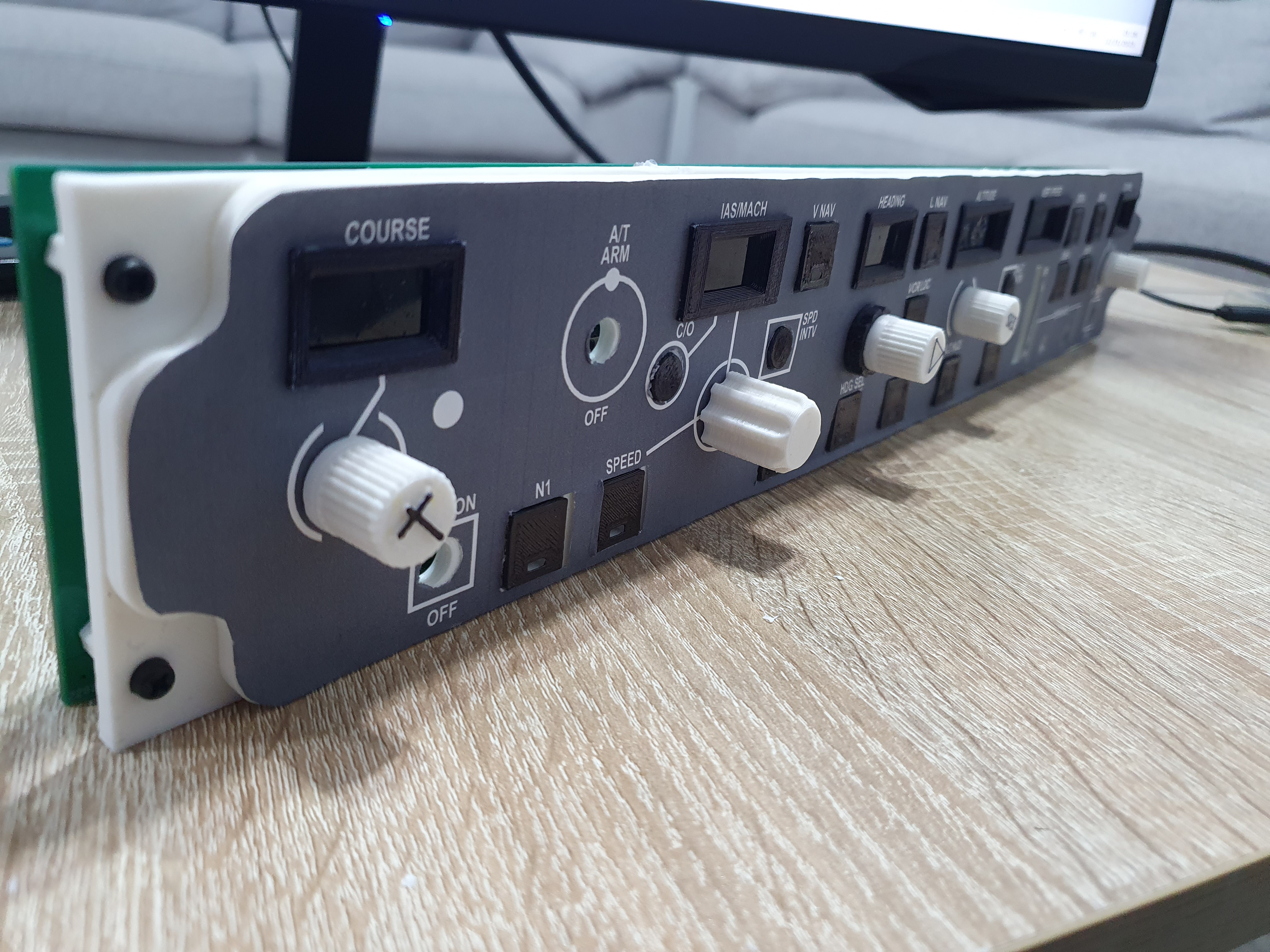
The best way would be laser engraving (or resin 3d printing) the faceplate, but since I am not familiar and don't own a laser myself neither do I own a resin 3D printer, I am designing the parts for normal 3d printing which is more difficult to achieve the desired look. Adding here also the different types of printers and printer settings.
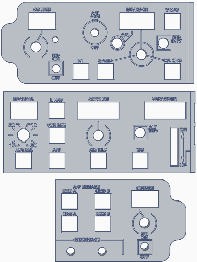
There are two versions:
* with text
* without text
To print the faceplate with text, you will need a 0.2mm nozzle otherwise you won't be able to get the text. If you are going with the text version, you need to paint the text with white marker.
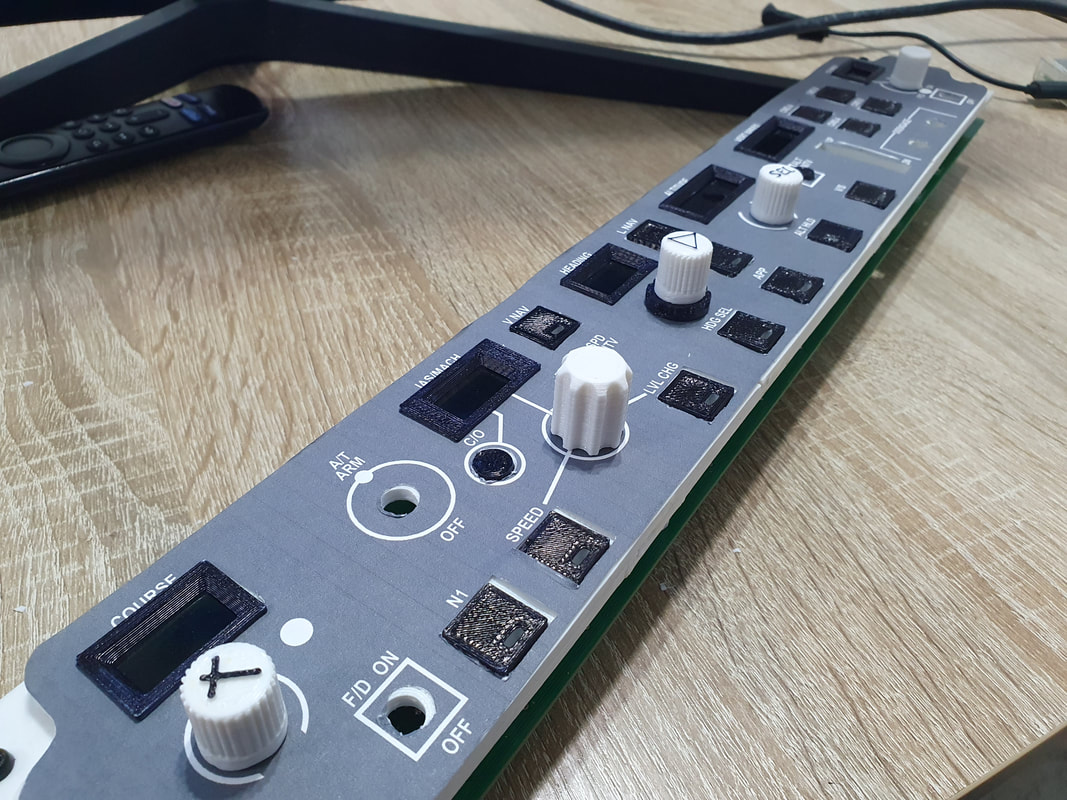
I will try to CNC the faceplate on alucobond and see the results, If it comes out good, I will print the text on a sticker, which should glue great on aluminum.
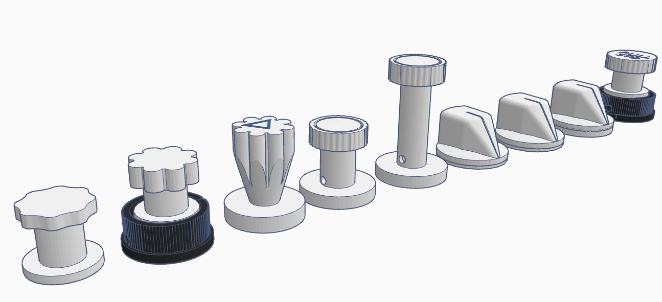
You need:
* 12 pcs of SquareButtonA (which is the normal square push button)
* 1 pcs of SquareButton (which is the VOR LOC push button with a piece cut off to not cause issues with the pinion of the banking knob)
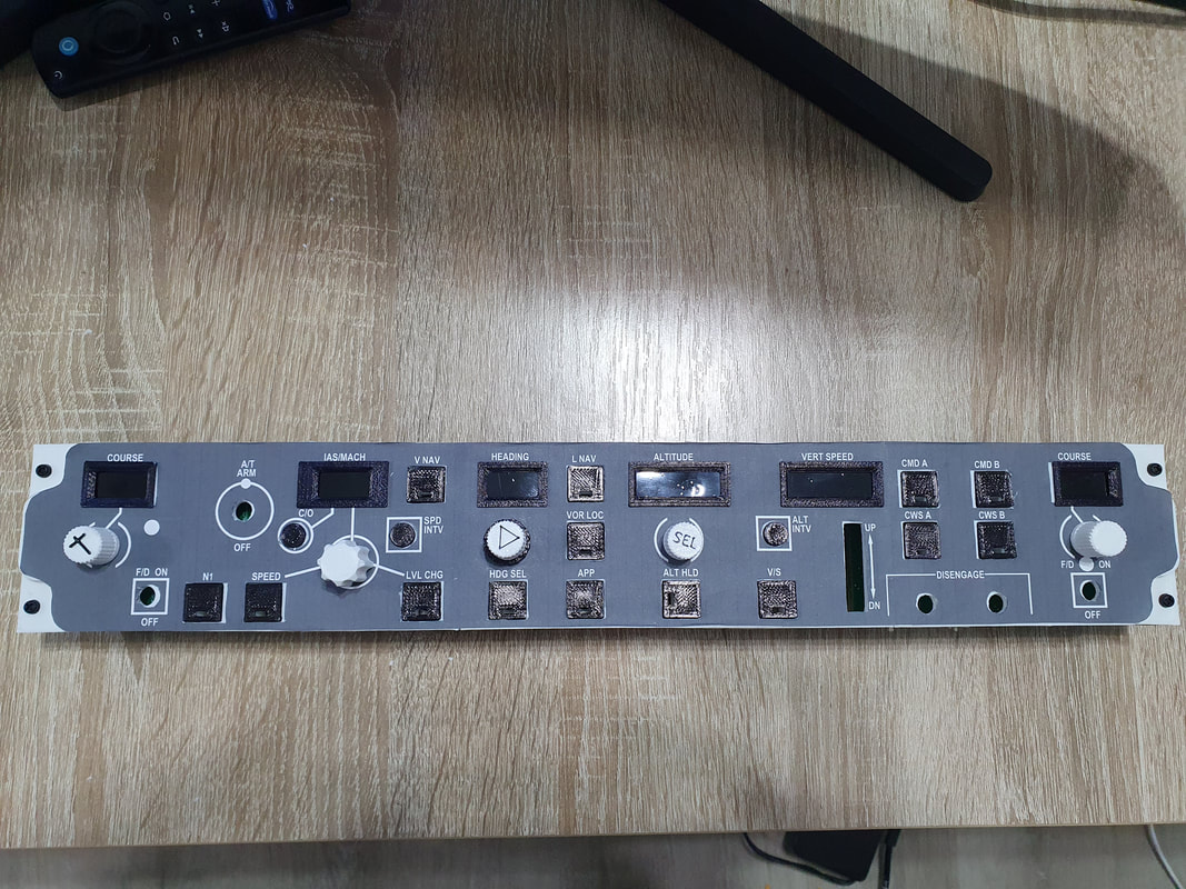
There are two versions:
* with text
* without text
To print the faceplate with text, you will need a 0.2mm nozzle otherwise you won't be able to get the text. If you are going with the text version, you need to paint the text with white marker.
I will try to CNC the faceplate on alucobond and see the results, If it comes out good, I will print the text on a sticker, which should glue great on aluminum.
You need:
* 12 pcs of SquareButtonA (which is the normal square push button)
* 1 pcs of SquareButton (which is the VOR LOC push button with a piece cut off to not cause issues with the pinion of the banking knob)
|
|
|

|
|
|
|
|
|
|
|
|
|
|
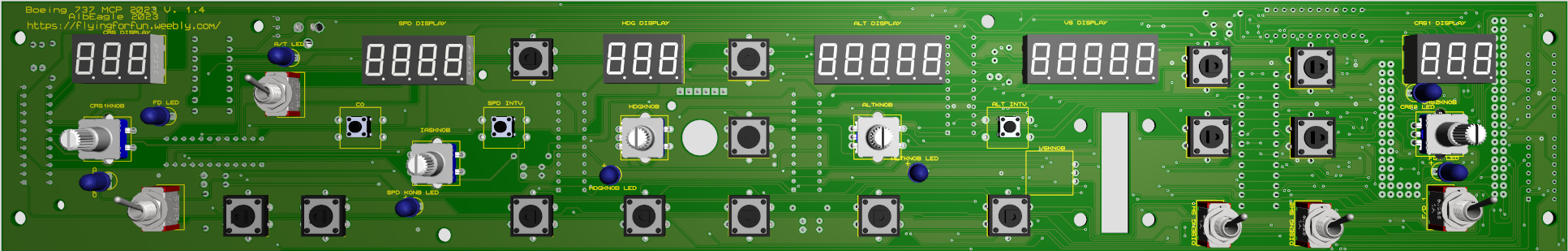
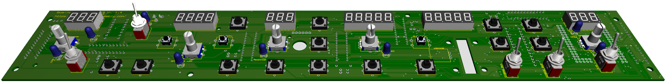
PCB V1.6
- CRS2- ALT- Encoder problem fixed
- Added pulldown resistors for the encoders
- Added pulldown resistors for the encoders
PCB V1.5
Notice: I have tracked an error on the PCB GND connections on the encoders which was caused by they program while designing it. It means the encoders grounds (except for the VS encoder) were not really connected to GND. That's why I have corrected that in V1.5. All those that have downloaded and already produced the V1.4 PCB's, they can just simply solder a wire from the middle pin of the encoders to any GND (they can of course have the V1.5 as well, just let me know).
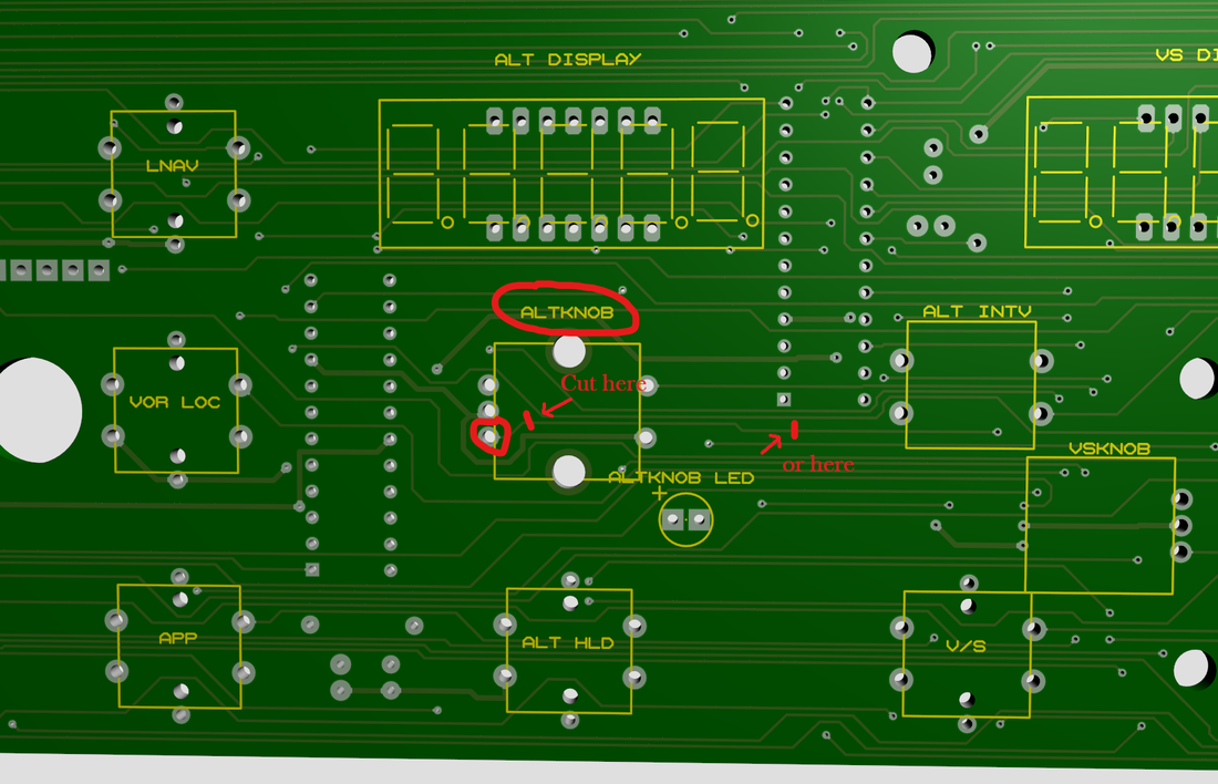
There is still an error where ALT- is by mistake taken to CRS2-. This has been fixed in V1.6. For V1.4 and 1.5 to correct that issue, you need to cut the ALT- Track and solder a wire from there to the Pin D11 on the arduino board pins.
There is still an error where ALT- is by mistake taken to CRS2-. This has been fixed in V1.6. For V1.4 and 1.5 to correct that issue, you need to cut the ALT- Track and solder a wire from there to the Pin D11 on the arduino board pins.
On the front side of the PCB, find the ALTKNOB encoder and cut the ALT- track as shown in the picture below. Find the most comfortable place you feel you can cut the track.
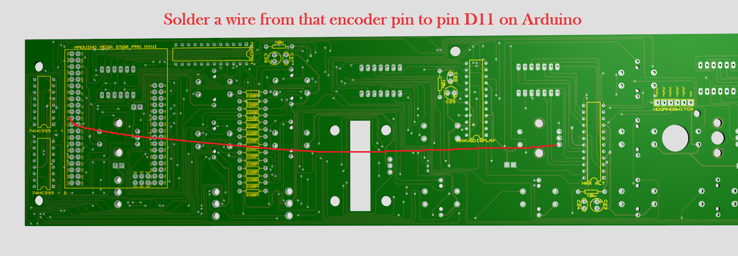
On the back of the PCB, find the ALT- pin as shown in the picture below and solder a wire from there to pin D11 of arduino board.
PCB V1.4
|
|
|
|
|
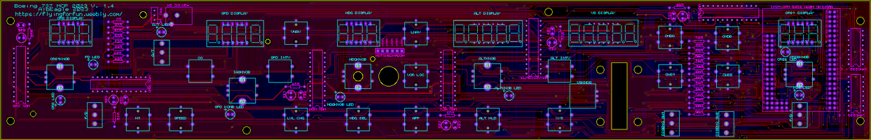
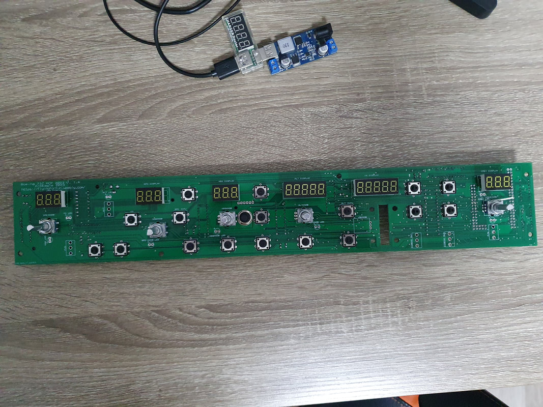
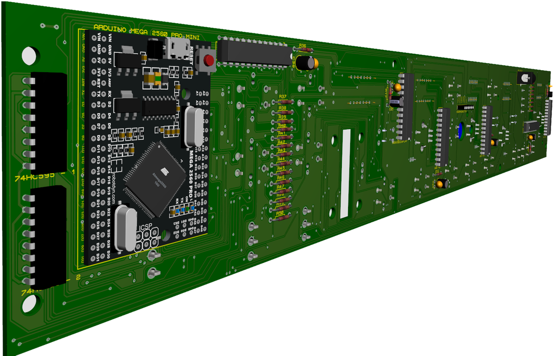
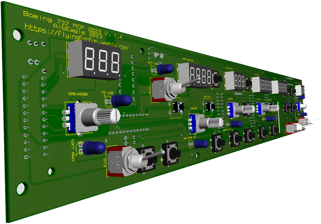
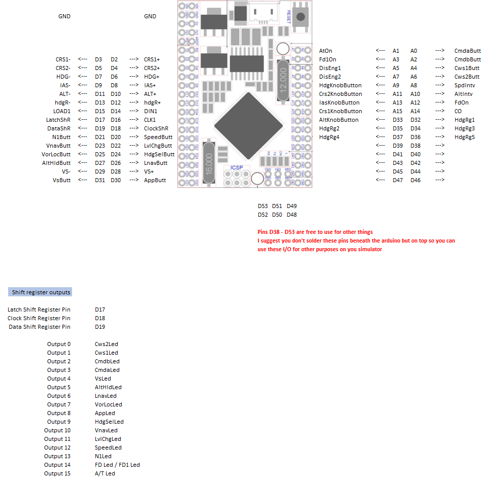
Pinouts
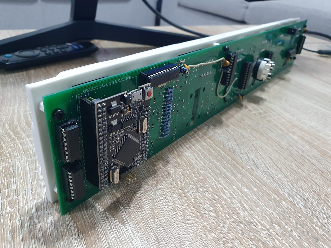
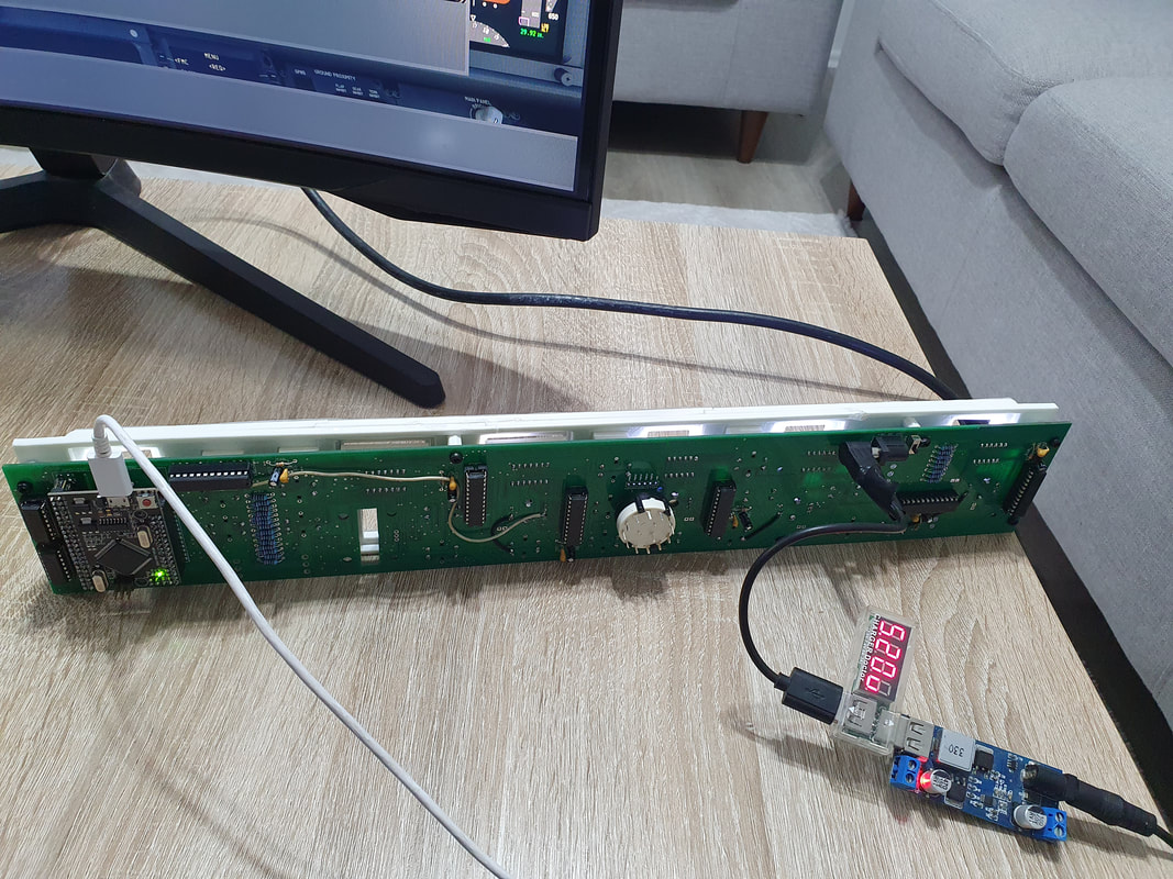
In the "Downloads" page you will find the gerber files of the Boeing 737 MCP to produce the PCB. I haven't built the MCP myself (it was built from other simmers on the net). Basically the same principle as the Cessna 172 Radiostack. You need an Arduino to program with Mobiflight and connect it to the board. The parts are listed in the parts_list.xlsx file below together with the links. I have etched the the Cessna 172 PCB's at jlcpcb.com and have had great service. I'm not in any way affiliated with the company so the choice is yours where to print them.
| Boeing_737_V1.6_Pinouts.xlsx |
Parts list
Parts list working as of today (19.09.2023)
| Boeing_737_BOM.xlsx |
2015, Copyright AlbEAGLE
